Understanding Electricity. Electricity is hard to explain because you can’t see it. In order to understand even the basics of electronics, you must first understand what electricity is. After all, the whole purpose of electronics is to get electricity to do useful and interesting things. CURRENT is identified by I and measured in amperes. Current flows from negative material to positive material and is essentially the number of electrons per second that are carried through a conductor.
Understanding what is a ground is one of the first things you will require to understand. Household wiring has two different paths to ground. The first path is generally called a “white wire ground” (the common conductor or neutral). This grounded wire is part of every household circuit. The second wire is an emergency path to ground for safety, called “the earth ground” .
The ground conductor is a bare, or green insulated, copper wire found in most household wiring. Non-grounded appliances have double-insulated jackets, which means that there is two different layers of insulation between live wires and any grounded parts within the appliance. Electricity moves easily through most metals and even through tap water, rainwater, and people. Anything that allows electricity to flow through it easily is called a conductor
In physics and electrical engineering, a conductor is an object or type of material which permits the flow of electric charges in one or more directions. For example, an insulated wire is an electrical conductor as it can carry electricity along its length (but not across its width). It is considered the conductor and is a bare, or insulated, copper wire found in most household wiring. Non-grounded appliances have double-insulated jackets, which means that there is two different layers of insulation between live wires and any grounded parts within the appliance.
The black wire in a 120 VAC circuit system is the hot conductor. This is the wire that powers your appliances and lights. It also ties into a fuse or circuit breaker in Your panel. You should always place switches or fuses on the hot wire rather than on the neutral wire. That way when the switch is open or the fuse/breaker trips, the current will be prevented from proceeding.. This minimizes any risk of shock that might occur if a wire comes loose within your project.
Electricity is transmitted through a cable in much the same manner as water in a pipe. Add more water at one end of the pipe and water is forced out the other end. We can move energy along a wire by giving energy to an electron at one end of the wire resulting in energy being moved along the length of the wire.
Most solid materials are classified as insulators because they offer very large resistance to the flow of electric current. Metals are classified as conductors because their outer electrons are not tightly bound, but in most materials even the outermost electrons are so tightly bound that there is essentially zero electron flow through them with ordinary voltages. Some materials are particularly good insulators and can be characterized by their high resistivities:
Ontario Electrical Code Update – Please visit CSA’s website for exact rules for electrical codes in Canada
2012 Canadian Electrical Code, Part I (CEC)
Top Fifteen changes of the 2012 Code
2009 CEC – Required in dwelling units 2012 CEC – Expanded to child care facilities
Description:
First introduced in the 2009 CEC, the 2012 CEC has now extended the requirement for
tamper resistant receptacles to child care facilities. This requirement intends to reduce
electrical injuries to children who may try to insert objects into wall receptacles.
Statistics indicate that for children less than 20 years of age, roughly 2/3 of electrical
injuries were sustained by children aged 5 years or less and 44 percent of the injuries
were sustained from the insertion of a conductive item or finger into a receptacle.
Unless otherwise defined by a regulatory authority having jurisdiction for child care
facilities, the Code intends that this requirement apply to child care facilities in areas
designed to provide care to persons seven years of age or less.
Tamper resistant receptacles are identified by the mark “TR” or “Tamper Resistant”.
2009 CEC – Electric vehicles covered by Section 86.
2012 CEC – Section 86 revised and rules added to Sections 8 and 26.
Description:
As electric vehicles become more commonplace, increased standardization has become
critical to ensure that electric vehicle charging infrastructure is properly addressed in
terms of safety, capacity, and consistency. The 2012 CEC fulfills this need through new
and enhanced rules governing the safety, load calculation, and installation of electric
vehicle charging equipment.
2009 CEC – No specific requirement existed.
2012 CEC – Rules added to require receptacle for garage door openers. Description:
2) Electric vehicles.
3) Garage door openers.
1) Tamper resistant receptacles. Unless otherwise specified at the time of construction, the garage in most homes is not
provided with an electric power door opener. However, it is common for homeowners to
install a garage door opener several years after the home was constructed. Since the
door opener was not installed during initial construction, it is highly unlikely that the
necessary receptacle was provided. In this case, the homeowner will either have a
contractor install a receptacle or connect the door opener to a wall receptacle with an
extension cord. The 2012 CEC requires that a receptacle be provided for each cord connected overhead garage door opener in residential garages.
2009 CEC – No specific requirements.
2012 CEC – “Splash pads” added to definition of “pool”. Description:
“Splash pads” are an increasingly popular form of outdoor water recreation found at
many community centres and public parks. Unlike a traditional pool, splash pads do not
contain any appreciable depth of water. However, they are used by persons with bare
feet on wet surfaces, similar to decks around swimming pools. Accordingly, the 2012
CEC now classifies splash pads as pools and mandates protection such as ground fault
circuit interrupters where applicable.
2009 CEC – Contained requirements for photovoltaic systems.
2012 CEC – New section added for renewable energy systems. Description:
The expanding market for renewable energy systems led to a need for Code rules to
help ensure safety for consumers and a level playing field for installers. New CEC
Section 64 addresses the unique installation requirements for a variety of renewable
energy systems including wind, hydrokinetic, micro-hydro and fuel cells. Existing
requirements for solar power have been updated considerably to reflect new
technologies, techniques, and calculations.
2009 CEC – No requirements
2012 CEC – Receptacles for maintenance purposes required.
Description:
Health and Safety, labour, and contractor associations identified a need for a roof-top
receptacle in order for HVAC (heating ventilation and air-conditioning) technicians to
safely maintain roof top equipment. The resulting Code rule will allow the technician to
disconnect power to roof top equipment while having safe access to a nearby receptacle
for purposes of illumination, test equipment, and power tools.
4) Splash pads.
5) Photovoltaic and Renewable energy systems.
6) Electrical facilities for maintenance of roof top equipment.Page 3 of 5
2009 CEC – Weather proof receptacle covers required.
2012 CEC – Weatherproof receptacle covers required to be weatherproof “in use”. Description:
Weatherproof receptacle covers provide protection from the weather when in the closed
position. However, the cover must be open in order to plug in an appliance or other
equipment. When the cover is open, the same level of protection from the weather is not
achieved and the receptacle is exposed to potential corrosion or water damage. The
new 2012 Code Rule requires that weatherproof covers provide protection from the
weather, even when an appliance is plugged in (when the receptacle is “in use”). Such
receptacle covers are identified by the words “wet locations”.
2009 CEC – Not specifically recognized.
2012 CEC – Requirements for installation added. Description:
Traditionally, switches and receptacles are installed in boxes that are installed during the
“rough-in” stage of an electrical installation. “Self contained” receptacles and switches
are manufactured with an integral box, meaning that a box is not required to be installed
during rough-in. Such devices are commonly used in the manufactured home industry.
2009 CEC – Location of heat controls not specifically covered.
2012 CEC – Specific requirements added to Section 62 of the Code.
Description:
Given the inherently wet environment in bathrooms, the Code contains specific
requirements for the location of switches and receptacles, and includes provisions for
protection by a GFCI (ground fault circuit interrupter). The 2012 Code now extends
these requirements to electric heat controls that are located within bathrooms.
2009 CEC – No specific requirements.
2012 CEC – Requirements for ceiling fan outlet boxes added. Description:
CSA standard C22.2 No. 113, “Fans and Ventilators” requires that ceiling fans be
provided with #10 screws for mounting to a ceiling outlet box. Ceiling outlet boxes
specifically designed for this purpose are available in the market and new Code Rules
will help ensure that where used, such boxes are installed correctly.
8) Self-contained wiring devices.
9) Electric heat controls in bathrooms.
10) Outlet boxes for ceiling fans.
7) Protection of receptacles exposed to the weather.2009 CEC – Grounding conductors sized in accordance with Table 17.
2012 CEC – Table 17 deleted.
Description:
Previous code editions required that the grounding conductor be based on the ampacity
of the service conductors. Based on further evaluation of the grounding conductor and
it’s intended purpose, it was determined that the system grounded conductor would carry
the majority of fault current and that a #6 AWG grounding conductor would sufficiently
fulfil the intended purpose during fault conditions.
2009 CEC – contained definitions for GFCI and ground fault protection.
2012 CEC – contains new and expanded definitions.
Description:
The new code definitions clearly delineate differences between ground fault circuit
interrupters intended to protect from shock (Class A type) and those that may be rated or
set at a ground fault current higher than that specified for Class A types. New definitions
also cover equipment that is only intended to indicate or warn that a ground fault has
been detected, as well as equipment that is designed to protect equipment from
damaging ground fault currents.
2009 CEC – Classified areas specified within the rules.
2012 CEC – Classified areas set in table form and aligned with gas standard.
Description:
Similar to gasoline dispensing stations, hazardous locations exist in the vicinity of
compressed natural gas refuelling stations, compressors, and storage facilities. A new
table has been added to the code to more clearly set out the area classification around
various components of such facilities. Values within the new table have also been
revised to align with CSA standard B108, Natural Gas Fuelling Stations Installation
Code.
2009 CEC – Required contact visibility in open and closed positions.
2012 CEC – Requires visibility in open position only. Description: 14) High voltage disconnecting means
13) Classification of hazardous areas around natural gas facilities 12) New terminology for ground fault detection and protection 11) Grounding conductor size Page 5 of 5
Due to the increased electrical hazards associated with high voltage installations,
disconnecting means are required to have contacts that are visible when in the open
position. In addition to other safety protocols, this feature provides operators with a
visual confirmation that there is an air gap between the line and load contacts. By
mandating visibility only in the open position, the Code now permits greater application
of switching technologies employing new and innovative technologies for viewing the
contacts. Such equipment is often more compact, resulting in a smaller footprint and an
increase in revenue producing square footage within buildings.
2009 CEC – Conductor ampacities determined by installation environment.
2012 CEC – Conductor ampacities determined by environment, equipment, and are correlated with NEC ampacities. Description:
The Rules and Tables for determining conductor ampacities have undergone a major
overhaul and have been correlated with the US National Electrical Code. Depending on
the individual installation, higher ampacities are permitted. However, the 2012 Code
also recognizes that conductors act as a “heat sink” for overcurrent devices such as
circuit breakers. Accordingly, new Rules may affect the ampacity of conductors
connected to equipment marked with a maximum conductor termination temperature.
15) Conductor ampacities
2009 CEC – Conductor ampacities determined by installation environment.
2012 CEC – Conductor ampacities determined by environment, equipment, and are correlated with NEC ampacities. Description:
The Rules and Tables for determining conductor ampacities have undergone a major
overhaul and have been correlated with the US National Electrical Code. Depending on
the individual installation, higher ampacities are permitted. However, the 2012 Code
also recognizes that conductors act as a “heat sink” for overcurrent devices such as
circuit breakers. Accordingly, new Rules may affect the ampacity of conductors
connected to equipment marked with a maximum conductor termination temperature.
Are Green Energy Sources Better Than Others. Did you know that green energy can help you to pay less for your electric and gas bills? You can also use less money in cleaning products. Green energy can help you save a lot of money, if you know the right ways to use it wisely. Here are a few ways that you can use green energy today.
In order to save extra energy around the house, be sure to set your electronics to a power-saving mode when not using them. A power-saving mode will reduce the amount of energy spent by the device. This way, you can save energy and cut down the cost of the electric bill.
Use light bulbs that are energy-efficient. Conventional light bulbs use entirely too much energy and create a lot of heat. Energy-efficient bulbs last much longer and don’t give off that much heat. They can sometimes give off dimmer light, so make sure to use as many as you need in your rooms so you have comparable amounts of light.
Turn your water heater temperature down. Setting the temperature at 120 degrees will still allow steaming hot water to come out of your faucets and showers, but you will save on your energy bills. According to research, for each 10 degrees you lower your water heater thermostat, you can save about three to five percent on energy costs.
If you have a tank-style water heater that you aren’t prepared to replace yet, conserve electricity or natural gas by lowering its thermostat. By changing the thermostat from the factory-set 140 degrees to 120 degrees, the heater requires 6 to 10 percent less energy to keep your water hot.
Make sure your dishwasher, washing machine, and clothes dryer are full (but not overfilled) prior to using them. This saves a lot of water and detergent with each load of wash. Also check the settings on these machines. If you have a small load, make sure the setting for small loads is being used.
Measure the prevailing wind speed on your property before considering a wind generator. In order for wind energy to be cost-effective, you need a wind speed greater than 8.5 to 9 MPH at least sixty percent of the time. Any slower, and the turbine won’t spin fast enough to generate much electricity.
If you simply cannot afford to upgrade or replace any part of your home’s energy systems, then change your energy-using habits instead. For example, take short showers instead of long baths and only wash maximum capacity loads of clothes or dishes to cut back on water consumption. Likewise, shut off any lights or appliances before leaving a room.
Finding the green energy technology information is only the first step in creating a home that is qualified to be considered a green home. Find the products that you can make work in your home and reduce your bills, as well as, your carbon footprint by making these positive changes.
Power Line Clearances. The Canadian Electrical Code Part I gives electrical utilities an exemption from the code for “installations and equipment in its exercise as a utility, located outdoors or in buildings or sections of buildings used for that purpose.” The CEC Part I is “a voluntary code for adoption and enforcement by regulatory authorities.” When adopted into the provincial regulations, this exemption is almost always maintained for work that falls within the scope of an electrical utility’s business.
Over time, many electrical utilities have either developed their own design standards or use standards developed by others. Two CSA standards are often used as authoritative references for utility installations. These are CAN/CSA-C22.3 No. 1- M87 Overhead Systems and C22.3 No. 7-94 Underground Systems. In some instances, utility standards may meet or exceed electrical code requirements, or they may also fall short. One would hope that utility standards should satisfy minimum electrical safety requirements, especially for installations on private property.
In a brave new world of less regulation and greater competition, electrical utilities may want to take a closer look at their own design standards, to determine whether they should conform with the Canadian Electrical Code. In this article, we will look at some examples where the CEC Part III standards fail to meet the minimum safety requirements of the CEC Part I, and visit another issue that might affect electrical utilities as changes evolve.
Let’s begin by comparing some of the differences in high low and high voltage clearances. I will refer to the Canadian Electrical Code as CEC Part I and the CSA Part III overhead standards as CEC Part III. Both prescribe minimum horizontal and vertical clearances for a broad range of voltage classifications. As an aside, there are a few instances where the CEC Part I actually references CEC Part III when an installation strays beyond the parameters set out in the code. As a result, some paragraphs of CEC Part III actually become requirements of our electrical code.
For our first example, CEC Part I specifies a minimum vertical clearance of 4.0 m for low voltage service conductors across a residential driveway. This increases to 5.0 m when crossing the driveway to a commercial or industrial facility. Using the same example, CEC
Part III would require minimum clearances of 3.7 m for low voltage service conductors across a residential driveway, and 4.42 m crossing the driveway to a commercial or industrial facility. Obviously, there is some disparity between the two standards.
CEC Part I specifies a minimum vertical outdoor clearance of 7.0 m for 46 kV exposed live parts such as cable terminations, fuseholders and switches, located outside a substation fence. CEC Part III has different requirements for areas accessible only to pedestrians and where there is also access by vehicles. The comparable 46 kV CEC Part III clearances would be:
• 3.7 m – where accessible only to pedestrians
• 5.2 m – where also accessible to vehicles
Here there appears to be a major difference between these standards for the elevation of high voltage exposed live parts.
Horizontal clearances between power lines and buildings is another place where there are differences. CEC Part I, requires a minimum 3 m horizontal distance between 46 kV lines and buildings (still far too close in this writer’s opinion). However, CEC Part III goes even further. Here the minimum horizontal distance between 46 kV lines and buildings is 1.0 m plus conductor swing to “a normally inaccessible surface” and 1.8 m plus conductor swing to a
“readily accessible surface.”
The CEC Part III definition of readily accessible is “that an object is accessible to persons without the use of special means” (for example, a ladder). The amount of conductor swing depends upon whether the line is considered to be sheltered from the wind. In the writer’s opinion, the horizontal clearances in both CEC Part I and Part III are both deficient.
However the CEC Part III requirements have a greater potential for problems and electrical accidents.
A further requirement of CEC Part I is calculating the 5000-volt maximum ground potential rise, and the step and touch voltages in substations. These are determined from the ground electrode resistance and the available ground-fault current. The first step normally involves ground resistivity measurement, then calculating the maximum step and touch potentials as specified in Table 52 of CEC Part I. Parameters for these calculations are found in the IEEE No. 80 substation grounding standard.
Ground potential rise can be calculated from station ground resistance and the available ground-fault current. Some electrical utilities are more interested in minimizing ground potential rise, since the GPR may affect any communications equipment installed in stations.
Step and touch potentials have also been identified as a safety issue and therefore should be considered as well.
For the reasons mentioned, electrical utility installations should comply with the Canadian Electrical Code Part I, particularly on customers’ property. As with previous articles, you should consult the electrical inspection authority in each province or territory as applicable, for a more precise interpretation of any of the above.
Always consult your local utility for their regulations regarding clearances or installation.
The Barrie Home Inspector has many more articles on electrical issues and regulations that would be of interest to most home owners.
Light is basically divided into two categories for the purpose of thermal imaging, visible light and invisible light. There is an almost infinite range of light beyond human range of vision. Light, as described in physics, is an electromagnetic wave that propagates through space at a fixed speed. This wave is further identified by its wave length, frequency and energy. As displayed below the actual wavelengths visible to the human eye is quite small.
As shown by the above graphic, human only see light in the wavelength range from 400 to 750 nm (nanometers). X rays and Gamma rays were initially thought to be particle rays rather than light rays, hence the terms rays. Radio waves are an example of low-energy light waves, and they are often described in terms of their frequency.
A prism placed into a ray of sunshine in a dark room reflects the colours of the rainbow using a property known as dispersion. This is the method Sir William Herschel utilized in the 1800’s in conjunction with thermometers to discern the presence of invisible light rays. He called his discovery the “thermometric spectrum” later to be known as infared.
This is the beginning segment of Thermal Imaging….more to come
Leading and Innovating in the Home Inspection Field, call the Barrie Home Inspector when purchasing your next property.
The Dirty Bakers Dozen of Residential Electrical Problems
Electrical Problems by Don Hester
The Dirty Bakers Dozen of Residential Electrical Problems- Wenatchee and Cle Elum Home Inspection Services
Are you a closet electrician? Many people including homeowners, mechanics, handymen, and engineers think they are weekend electricians. By what is observed it is obvious that many times this work is beyond the comprehension and understanding.
As a professional home inspector I am looking for these repairs and installations which create shock hazards and potential fire hazards.
The National Electrical Code (NEC) is the rules which all electricians operate under. There can be many local interpretation and revisions in force around the country, but for all intents and purposes this is the minimum standard for safety in electrical systems. Wiring and installations that do not comply with these standards could end up in fire or severe shock, it does happen.
Home electrical fires
In 2009, an estimated 44,800 home structure fires reported to U.S. fire departments involved some type of electrical failure or malfunction as a factor contributing to ignition. These fires resulted in 472 civilian deaths, 1,500 civilian injuries, and $1.6 billion in direct property damage.
Home electrical distribution or lighting equipment fires
In 2009, an estimated 21,000 reported U.S. non-confined home structure fires involving electrical distribution or lighting equipment resulted in 320 civilian deaths, 1,000 civilian injuries, and $935 million in direct property damage.
Here is a list of common electrical problems found in a typical home inspection. They are not in any particular order.
Three Prong outlets improperly wired (no ground provided)
Ungrounded circuits are converted to accept a newer 3 prong outlet. This gives the illusion that the receptacle is grounded but is not. Properly grounded outlets allow stray current to travel to the earth ground if a malfunction occurs.
Hot-Neutral Reverse
This is another commonly found issue during a home inspection where the receptacles are improperly wired that has the polarity of the outlet is reversed. This means the small slot on the receptacle that should be the hot is now the neutral and the large slot is hot which should be the neutral. This creates the potential for shock.
“Homeowner” wiring (or is it Uncle Bob?)
Performed by homeowners or handymen they hired there is usually several signs of unprofessional work performed. Inspectors find, hanging wires, open junction boxes, splices not in boxes, inadequately sized wires and/or switches. During the home inspection I will find improperly wired 3 way switches, fixtures and devices.
Extension cords used as permanent wiring
Extension cords are used all the time. They should never be considered permanent wiring. Extension cords should never be installed under rugs or covered. Excess cord should not be bundled or rolled up when in use. They should periodically inspected to make sure they are not warm, overheated, brittle, cracked or damaged. Extension cords have “gauges” that should be properly sized for the load required. Undersized cords are a fire danger.
Oversized Fuses or Breakers
The fuse or breaker is supposed to be the weakest link in the circuit. If there is a “situation” you want the fuse to blow or the breaker to trip. By increasing the size of the breaker or fuse the homeowner has not increased the power to the circuit. They now have made the wiring in the wall or device the weakest link and could cause a fire. Think of it as turning the wires in the wall into heating elements.
Single Strand Aluminum Wiring
Houses built between 1960 and 1973 could have some single strand aluminum wiring. There was a copper shortage during this time which made copper more expensive. The inexpensive substitute was aluminum. The problem was that aluminum wiring expands and contracts at a different rate than copper. The devices that were connected to it were not designed to handle this causing loose connections that lead to fires. Aluminum also corrodes when it is in contact with copper. Needless to say there are tens of thousands of homes that have aluminum wiring. Replacement is the best option but may be expensive. There are approved connectors but need to properly installed to ensure they will work.
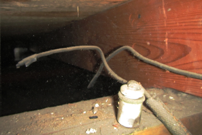
Knob and Tube Wiring
Many older homes have Knob and Tube (K&T) wiring which was one of the earliest type of residential wiring. K&T looks like individual cloth covered wired that are spaced approximately 8-12 inches apart. The wires are secured with ceramic knobs on framing members and ceramic tubes that go through framing members. Much of the problem with this system is when connections/splices are made to the system. Or the wiring is overloaded and should never be on anything but a 15 amp breaker or fuse. The wiring can become brittle and the solder joints can weaken. Again replacement is the best option but can be expensive.
No Ground Fault Circuit Interrupter (GFCI)
GFCI’s sense a fault to ground (this is a unintended ground path- shock) and cuts off power within 1/4th of a second. This means it’s off within 3-5 milliamps, which is before the average person would be seriously injured. They are required in all new construction for exterior, garage, unfinished basements, crawlspaces, bathrooms and kitchens. They can and should be retrofitted into all existing homes.
Worn out receptacles
Yes, receptacles wear out. If you plug a cord into an outlet and it falls out or is loose it is time for replacement. Worn out receptacles means the contact is poor and can now create arcing causing melting of the plug or fire.
Missing or broken junction box covers
This is another very common item. When junction boxes (outlets, switches or wire splices) cover is missing or broken the connections are exposed. They also will contain any sparking that can cause a fire to the junction box.
Zinsco or Federal Pacific Service Panels Federal Pacific (FPE), Zinsco, Zinsco-Sylvania, GTE-Sylvania or Kearny panels where manufactured for residential and commercial circuit breakers and load centers (panels) from the early 1950’s until the 1980’s.
Significant problems and failures have been documented with these panels and circuit breakers. The circuit breakers have a history of not tripping during a current fault. This can be a dangerous situation which can lead to fire and electrocution. Other common problems are melting buss bars, loose
In every case of these panels they should be thoroughly examined by an electrician. Replacement is highly recommended.
Unprotected Wiring
It is very common to find wiring in the home that is vulnerable to mechanical damage. This could be the old “Romex” under the sink or a cabinet or the new light fixture in the closet. Any wiring that is in a location that could be damages by stored goods or by hanging stuff from it needs to be protected.
Inadequate Service for today’s requirements
Most homes are built with a minimum electrical service. That’s always been true. But today with the 1500 watt dryers, microwaves, various appliances, and computers along with all the other conveniences we want the existing older services may not be adequate. This may be especially true if your services is 40 years old or older.
“One of the true tests of leadership is the ability to recognize a problem before it becomes an emergency.”
Arnold H Glasgow
NCW Home Inspections, LLC is a Licensed Washington State Home Inspection service located in Wenatchee Washington serving Chelan County, Douglas County, Kittitas County, Okanogan County and Grant County Washington and the cities of Wenatchee, Leavenworth, Cashmere, Orville, Cle Elum, East Wenatchee, Quincy and many more…
Your Wenatchee and Chelan Professional Real Estate, Home and Structural Pest Inspection Service